


Why the blade edge, not the antenna, is the only position that matters
An rtk gnss module for machine control is selected on different criteria from one used for surveying or mapping. The machine is moving, the antenna is vibrating, the body is pitching and rolling, and the hydraulic system is responding to the position output within milliseconds. A module that produces beautiful static data can still produce a rough grade if its latency, update rate, or attitude handling does not match the machine.
This guide covers what construction and industrial equipment actually needs from a GNSS module, how the position at the antenna is translated into a position at the cutting edge, why timing dominates grading quality, and which electrical and environmental details decide whether the installation survives a working season.
What Machine Control Demands That Surveying Does Not
Three characteristics separate the two use cases.
- Continuous availability replaces point accuracy. A surveyor can wait for a good fix. A dozer cutting a slope cannot. The module has to maintain a usable solution while the machine passes under a bridge, beside a stockpile, or through a cut where half the sky is blocked.
- Attitude is part of the position. The antenna sits on the cab roof; the blade is several metres ahead and below. Converting one to the other requires the machine's orientation, which means either an inertial unit or a dual-antenna heading measurement.
- Timing is a control parameter. A late position causes the control system to over-correct. At grading speeds, a latency difference of a few hundred milliseconds changes the surface the operator sees behind the machine.
Getting From the Antenna to the Blade Edge
Every machine control system performs a coordinate transformation from the antenna phase centre to the working edge: blade, bucket, drum, or screed. The transformation uses measured offsets in three axes plus the machine's roll and pitch.
The offsets are entered during commissioning and are only as accurate as the measurement. A 10-centimetre error in the fore-aft offset produces a 10-centimetre grade error that repeats on every pass, and operators typically compensate by adjusting the design surface rather than by re-measuring. That converts a mechanical error into a permanent systematic bias in the finished work.
Attitude is the harder half. An excavator cab rotates independently of the tracks; a dozer pitches as the blade loads; a grader's frame articulates. Each of these changes the vector from antenna to edge. A module that provides only position forces the system to depend entirely on inertial sensors, which drift and require calibration. A dual-antenna module that provides heading directly reduces that dependence, and on articulated machines it eliminates a whole class of calibration errors.
Update Rate, Latency, and the Hydraulic Loop
Machine control systems commonly run their control loop far faster than the GNSS output rate. The GNSS position is used as a low-frequency correction to a high-frequency dead-reckoning model driven by inertial and machine sensors. What the loop needs from the module is therefore not raw speed but predictability: a consistent delay that can be modelled and compensated.
| Machine type | Typical rate | Critical factor |
|---|---|---|
| Dozer | 10 to 20 Hz | Pitch compensation under blade load |
| Excavator | 10 Hz plus body sensors | Cab rotation and boom geometry |
| Grader | 10 to 20 Hz | Articulation and blade rotation |
| Paver or milling machine | 10 to 50 Hz | Smooth trajectory at low speed |
| Agricultural or industrial vehicle | 10 to 50 Hz | Path following at speed |
Ask the supplier for the timestamp behaviour of the output message. If the timestamp corresponds to the measurement epoch rather than the transmission time, the control system can compensate for latency correctly. If it reflects transmission, the compensation will be wrong by exactly the processing delay, and the error will grow with machine speed.
Interfaces and Correction Links
Machine control installations are rarely clean. The module usually shares a CAN bus with the machine's own controllers, receives RTCM corrections over a radio or a cellular link, and outputs both a position solution and a set of status flags to the display.
Three interface details deserve attention during design. First, the correction input must accept the RTCM version and message set your base or network actually broadcasts; adaptive recognition of the differential format removes a common commissioning problem. Second, the module needs a hardware timing output if the control system aligns GNSS with inertial samples. Third, the status output must distinguish between fixed, float, and single-point solutions, because the control system has to change its behaviour when the solution degrades rather than continuing to steer with an optimistic weight.
On a site with its own base station, the correction link is usually a UHF radio with limited bandwidth. Modules that handle a reduced message set gracefully, rather than dropping to float when a message is missing, are noticeably easier to deploy.
Electrical and Environmental Realities
Construction equipment supplies power that is neither clean nor stable. Alternator transients, starter surges, and welding on site all appear on the supply rail. A module intended for machine control needs input protection and a supply range that tolerates the vehicle's worst case, not its nominal case.
Vibration is continuous and broadband. Connectors work loose, solder joints crack, and mounting brackets fatigue. The module itself is usually less vulnerable than the antenna mount and the cable, which is why the mechanical design deserves as much attention as the electronics.
Finally, the RF environment on a machine is crowded. Radios, telematics units, and inverters all radiate. A module with built-in anti-interference capability — the kind that maintains tracking when a nearby transmitter is active — avoids a class of intermittent failures that are extremely difficult to diagnose after the fact.
Commissioning deserves its own procedure. Check the lever arm measurements against the machine drawings with a tape rather than trusting the as-built model, verify the tilt sensor zero on a level surface, and record the resulting residuals at three known points. A machine that grades consistently is almost always one whose commissioning was documented, because the same numbers can be re-entered when a sensor is replaced years later.
Yonghao Innovation Modules for Machine Control
Yonghao Innovation Tech is a national high-tech enterprise established in 2014, based in Shenzhen, Guangdong, China. We integrate research, manufacturing, and sales, and we supply GNSS satellite antennas, positioning terminals, data communication products, and customized high-precision BeiDou solutions for surveying and monitoring, aerospace, communication time service, autonomous driving, machine control, and intelligent transportation.
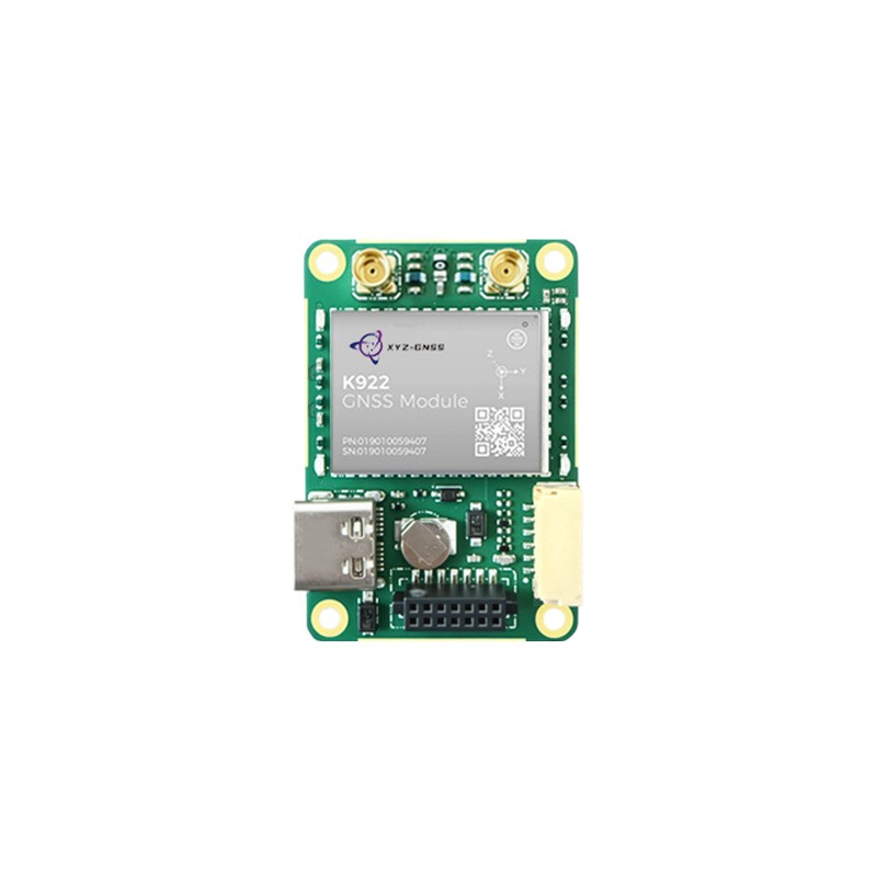
Our RTK GNSS module range includes engines suited to machine integration. The UM980 tracks all constellations and frequencies including BDS, GPS, GLONASS, Galileo, QZSS, NavIC, SBAS, and L-Band, with built-in multi-frequency anti-interference technology that improves RTK initialisation in obstructed conditions. The K922 supports full-system, full-frequency reception with RTK, PPP, and SPP modes plus an integrated IMU for on-chip combined navigation, which simplifies attitude-dependent control on vehicles.
Where the installation calls for a complete terminal rather than a board-level module, the RTK GNSS receiver range provides housed units with the same positioning engines. Our technical support team can review the interface, correction format, and power environment before you commit to an architecture.
Conclusion
The right rtk gnss module for machine control is the one whose timing, attitude support, and interface behaviour fit the control system, not the one with the best static specification. Predictable latency, honest quality flags, direct heading where the machine articulates, and tolerant electrical design determine whether grading is smooth or whether the operator spends the day correcting for the system. Verify those on the machine before the mechanical design is frozen, and the rest of the integration follows.
Tell us the machine type, control loop rate, and correction source, and we will recommend a module and interface configuration.
Review my machine design Compare module optionsFrequently Asked Questions
Q1: What update rate does an rtk gnss module for machine control need?
Most grading systems work well with 10 to 20 Hz, because the inertial system carries the high-frequency motion. Consistency of latency matters more than the headline rate; a predictable delay can be compensated, an irregular one cannot.
Q2: Does an rtk gnss module for machine control need dual antennas?
It depends on the machine. Articulated equipment and rotating cabs benefit most, because heading cannot be inferred from motion when the body changes orientation independently of the travel direction. Machines with a fixed geometry can often rely on inertial heading.
Q3: How is an rtk gnss module for machine control affected by vibration?
The electronics are usually robust; the failure points are the antenna mount, the cable, and the connector. A rigid bracket, strain relief, and a locking connector eliminate most vibration-related faults on construction equipment.
Q4: Can an rtk gnss module for machine control run on the vehicle's own power supply?
Only with protection. Vehicle rails carry starter transients and alternator noise well outside the nominal range. Specify a module with a wide input range and add transient suppression, particularly on machines where welding or jump-starting occurs.
Q5: How should an rtk gnss module for machine control behave when corrections drop out?
It should fall back to float or single-point operation and flag the change immediately. The control system can then reduce the GNSS weight or stop automatic blade control, which is far safer than continuing to grade on a solution whose accuracy has silently degraded.